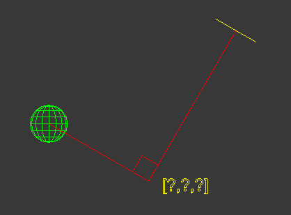
[Closed] rotating from center and normal
In this situation I’ve given a normal, a center position for the normal and I want to align the sphere along the vector of the other object, based on the normal. How would I do this?
/* Test Scene Setup */
delete objects
pln = plane width:5 length:5 pos:[10,10,10] wirecolor:yellow
rotate pln (angleaxis 30 [1,0,0])
s1 = sphere pos:[25,30,0] wirecolor:red radius:2
s2 = sphere pos:[32,18,7] wirecolor:green radius:1

center = pln.pos
normal = pln.transform.row3
1 – Get the distance between the big sphere and the yellow box.
2 – place the big sphere on the path(vector/direction) between the small sphere and the yellow box at the calcualted distance. No need of rotation.
–1 – Get the distance between the big sphere and the yellow box.
–2 – place the big sphere on the path(vector/direction) between the small sphere and the yellow box at the calcualted distance.
/* Test Scene Setup */
delete objects
clearlistener()
pln = plane width:5 length:5 pos:[10,10,10] wirecolor:yellow
rotate pln (angleaxis 30 [1,0,0])
s1 = sphere pos:[25,30,0] wirecolor:red radius:2
s2 = sphere pos:[32,18,7] wirecolor:green radius:1

center = pln.pos
normal = pln.transform.row3

-- step 1: Find Distance
dist = distance pln.pos s1.pos

-- step 2: vector dir
dir = normalize (s1.pos - pln.pos) -- not used

fn GetPlacement startPos endPos =
(
	startPos+(normalize (endPos-startPos)) * dist
)

p = GetPlacement pln.pos s2.pos
newS = sphere pos:p wirecolor:blue radius:1
No it doesn’t appear to work as expected. It just places the object along the vector, which doesn’t create the desired result as the image shows above.
If you want the big sphere to be aligned to the path using the Normal of the yellow box try this:
- create a matrix using the normal of the yellow object(Z of the matrix match the normal)
- project the spheres on the XY planne of that matrix
- measure the distnace between projected point of the big sphere and place it(on tne XY plane) or rotate id as you need.
your solution makes sense but im only familiar doing the first part. could you show how to do the rest?
This have to works, but for some reason this
newS1pos = stPos + (dist * dir)
not gives the point along the vector pln-s2.
(
	/* Test Scene Setup */
-- 	delete objects
-- 	pln = plane width:5 length:5 pos:[10,10,10] wirecolor:yellow
-- 	rotate pln (angleaxis 30 [1,0,0])
-- 	s1 = sphere pos:[25,30,0] wirecolor:red radius:2
-- 	s2 = sphere pos:[32,18,7] wirecolor:green radius:1

-- 	center = pln.pos
-- 	normal = pln.transform.row3

	pln = $Plane001
	s1 = $Sphere001
	s2 = $Sphere002


	function PointPlaneProj pA pB pC pD =
	(
		--	find the point on the plane ABC which is the projection of the point D
		local nABC=normalize (cross (pB-pA) (pC-pA))
		pD+((dot (pA-pD) nABC)*nABC)
	)
	--	"create the matrix"
	tmpMat = matrixFromNormal (pln.dir)
	tmpMat[4] = pln.pos
	in coordsys tmpMat
	(
		stPos = [0,0,0]
		projPosS1 = PointPlaneProj [0,0,0] [10,0,0] [0,10,0] s1.pos
		point pos:projPosS1
		projPosS2 = PointPlaneProj [0,0,0] [10,0,0] [0,10,0] s2.pos
		point pos:projPosS2

		dir = normalize (projPosS2 - stPos)
		a = point pos:stPos dir:dir wirecolor:yellow
		dist = projPosS1 - stPos
		newS1pos = stPos + (dist * dir)
		point pos:newS1pos wirecolor:green
		s1projPosDist = distance s1.pos projPosS1
		newS1pos.z -= s1projPosDist
		box pos:newS1pos
	)
)
Yeah this is surely a tricky one.
I’m wondering if there is an easier approach to the solution we are overlooking by chance… I’m still trying to find a solution here.
