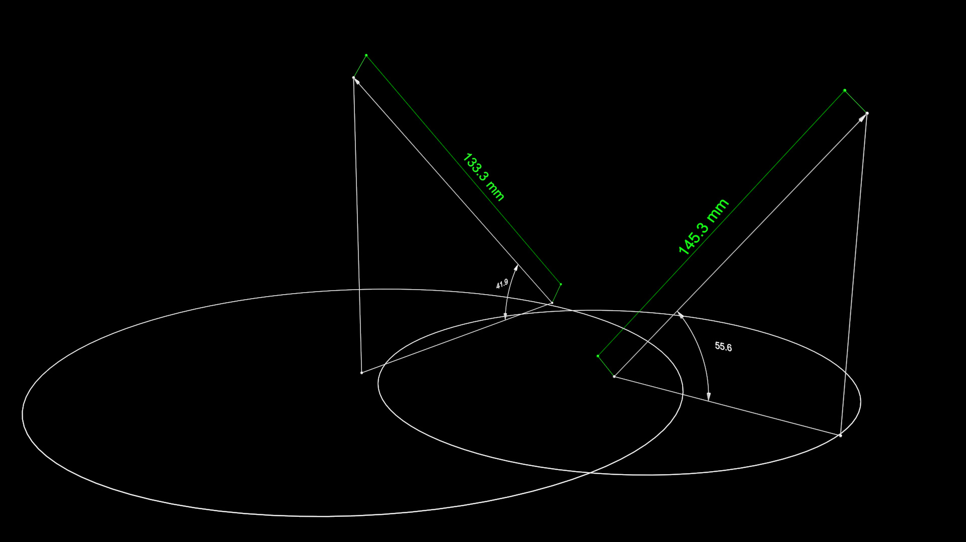
[Closed] Maxscript – autocad style
Sorry:
I made a mistake while copying the code. I attach the complete code.
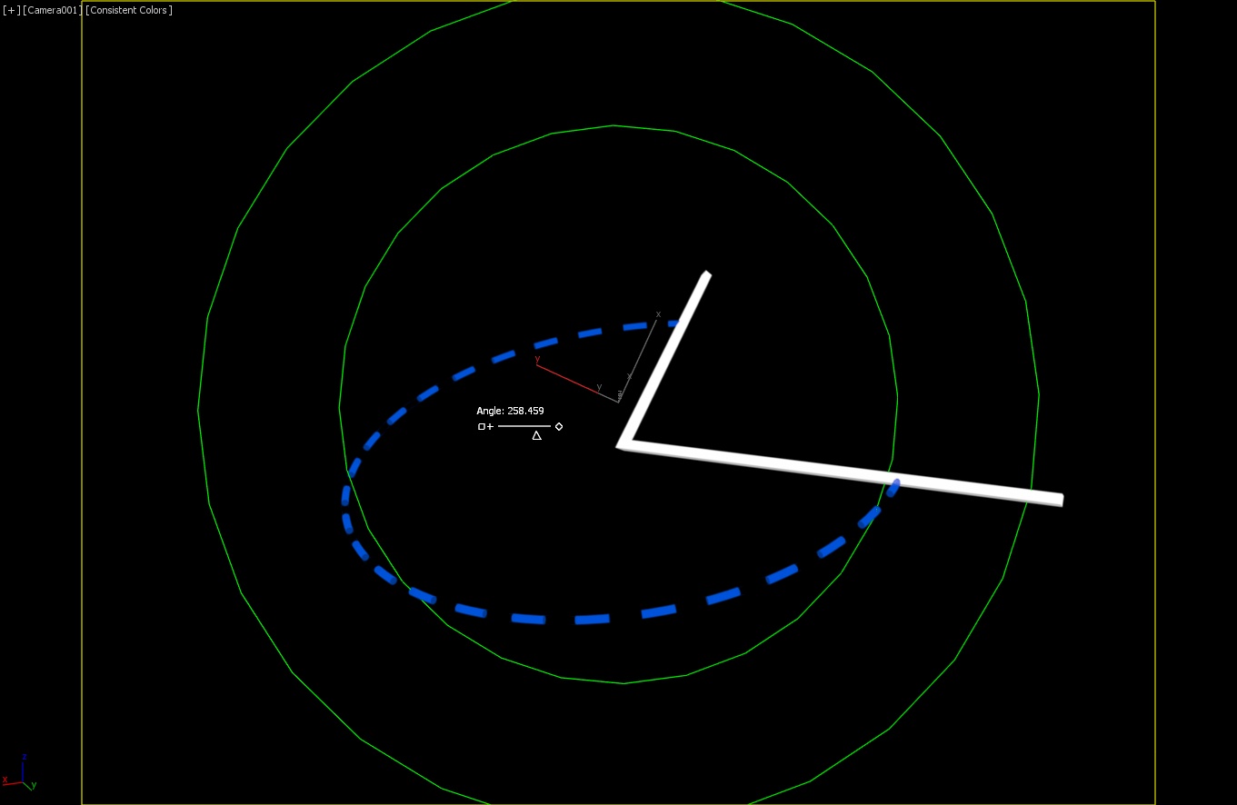
How can I place this code in a control for the position of the points, so that when moving the points, the Dash Lines are modified?
(

--Creating Big Line
SplineTarget = splineShape pos:[0,0,0] wirecolor:white name:"Spline_Target" render_renderable:false
addNewSpline SplineTarget
addKnot SplineTarget 1 #corner #line [0,0,0]
addKnot SplineTarget 1 #corner #line [150,0,0]
updateShape SplineTarget
animateVertex SplineTarget #all

WidthDash = 4 as integer
GapDash = 2 as integer
L = CurveLength SplineTarget as integer
CantidadDash = floor(L/(WidthDash+GapDash))  -- Integer
Dash=#() --Array for Spline small
ArrayPercent = #()  -- Array for Percent
-- Creating Dash Lines and Array of Percent
for i=0 to CantidadDash do
(
append ArrayPercent (i*(WidthDash+GapDash)) -- Generating list of Percent
append Dash (sp = splineShape pos:[0,0,0] wirecolor:green name:("Dash"+i as string) render_renderable:true thickness:0.3 sides:6)
addNewSpline sp
addKnot sp 1 #corner #line [0,0,0]
addKnot sp 1 #corner #line [0,0,WidthDash]
updateShape sp
animateVertex sp #all

)

-- Put Array of Lines on Spline
for i=1 to CantidadDash+1 do
(
Dash[i].pos.controller = path follow:true
PosCont = Dash[i].pos.controller
PosCont.path = SplineTarget
PosCont.axis = 2
PosCont.percent = ArrayPercent[i]
)

)I’m an engineer, and I use vectors a lot to describe phenomena and equipment designs.
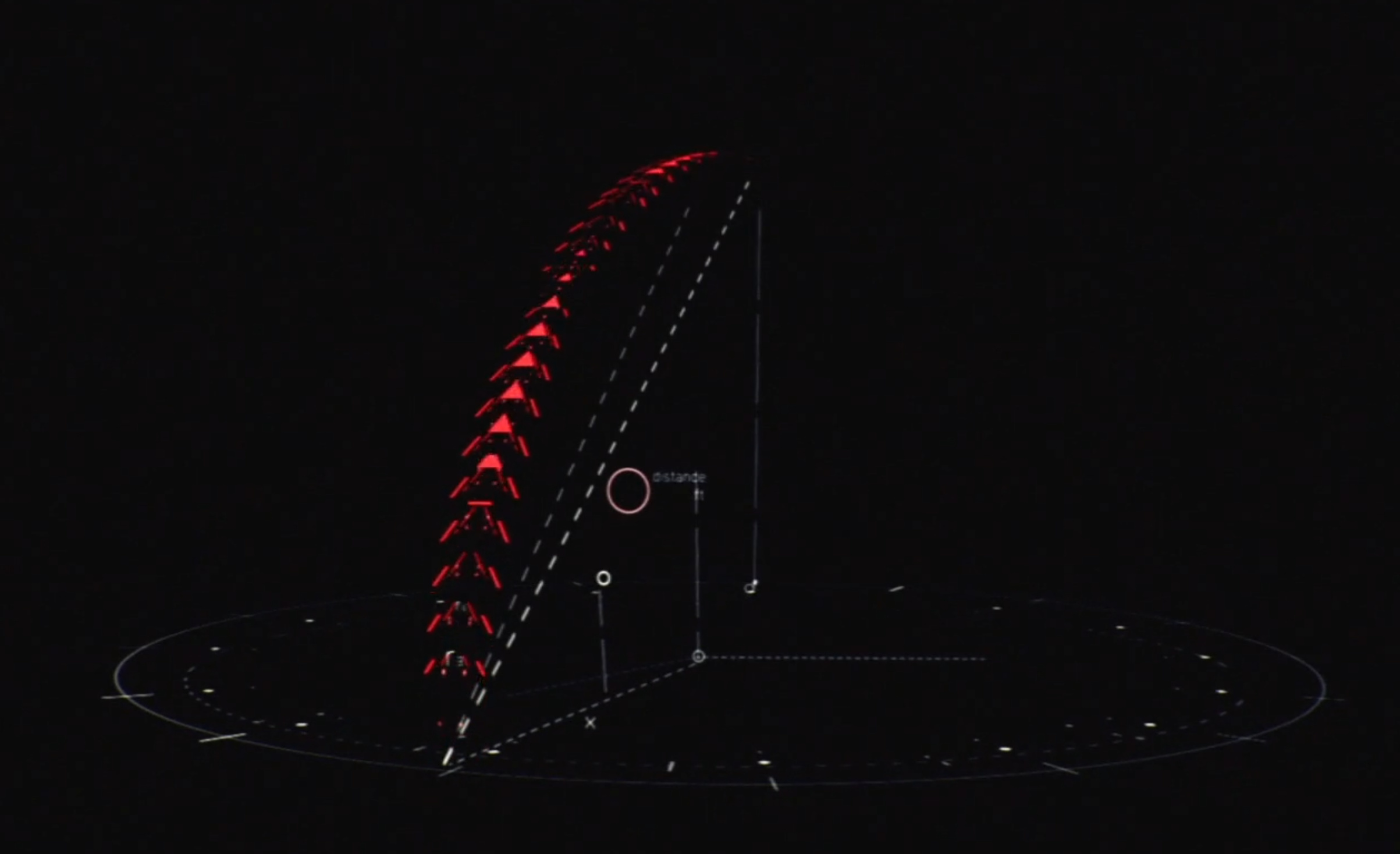
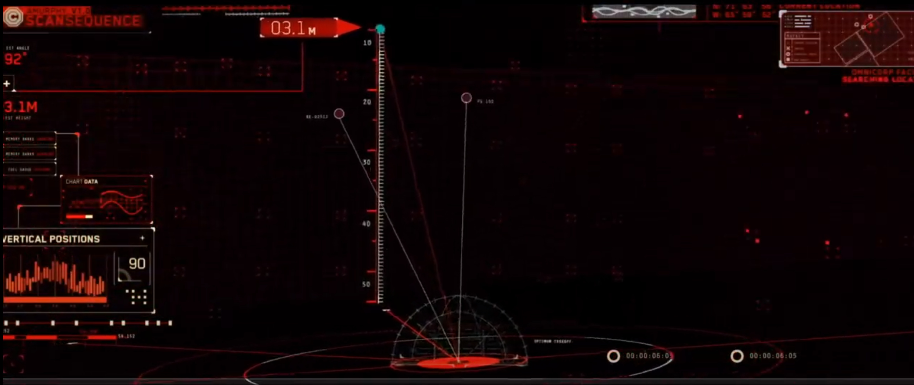
In Robocop Film, they use vector.
This can be done in After Effects, but the restriction is the manipulation of many 3d objects, it slows down the PC. I can render in 3ds Max, and then I make effects to make up the final video.
True
And here’s an example with base spline shp. named Arc
and checker map in opacity slot
UVW Xform mod. tile controller instanced on Arc angle ctrl to keep tilling consistent.
And sliderManipulator for billboard
You could have some difficulties with 3D and rendering to turn off all the default and usual things to get that ZX Spectrum effect, specially with “render_renderable:true”
From examples you’re showing you will have do “downgrade” even default Std “non-material” – “color” you see before assigning some “real” material/shader
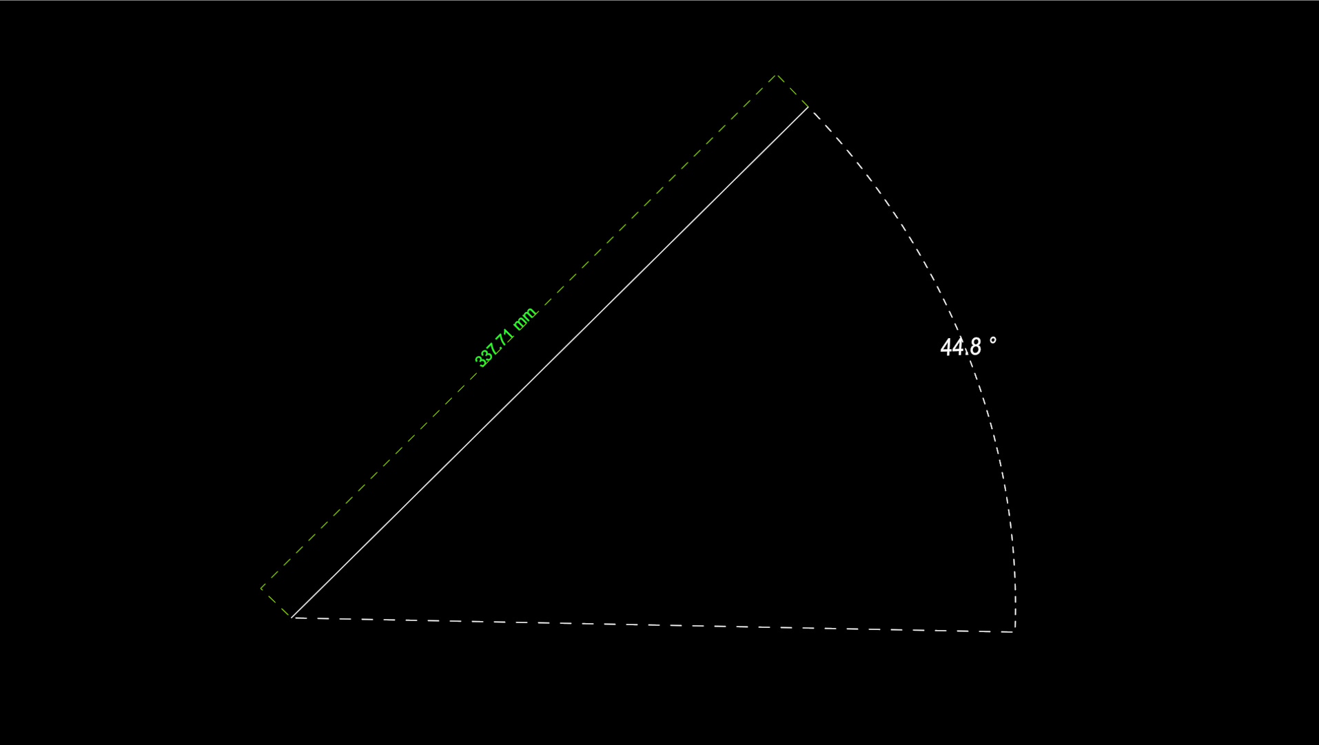
Hello everyone, I finally achieved what I wanted, only a few fixes are missing at the intersection points.
If you want to test the code there are 4 things to do.
- Assign material checker for dash lines.
- Move P1 from viewport (yellow)
- Move P0 from viewport (network)
- Link to the two texplus with the length and angle of the Arc
(
disablerefmsgs()
delete objects
enablerefmsgs()


P0 = point name:"P0" pos:[0,0,0] wirecolor:red size:50
P1 =  point name:"P1" pos:[200,0,0] wirecolor:Yellow size:50
P2 =  point name:"P2" pos:[200,0,0] wirecolor:green size:20
P3Aux =  point name:"P3aux" pos:[200,0,0] wirecolor:green size:5
Obj = Arc name:"TheAngle" from:0 wirecolor:white render_renderable:true thickness:0.4 sides:6 steps:16 render_displayRenderMesh:true render_displayRenderMesh:true

Obj.pos = P0.pos
P3Aux.pos = P2.pos
P3Aux.parent = P2

P0Ruler =  point name:"P0Ruler" wirecolor:green size:5
P1Ruler =  point name:"P1Ruler" wirecolor:green size:5
P2Ruler =  point name:"P2Ruler" wirecolor:green size:5
Desfase_Ruler = 20

P0RulerAux =  point name:"P0RulerAux" wirecolor:green size:5
P1RulerAux =  point name:"P1RulerAux" wirecolor:green size:5
P2RulerAux =  point name:"P2RulerAux" wirecolor:green size:5

P0RulerAux.pos = P0Ruler.pos
P1RulerAux.pos = P1Ruler.pos
P2RulerAux.pos = P2Ruler.pos

P0RulerAux.parent = P0Ruler
P1RulerAux.parent = P1Ruler
P2RulerAux.parent = P2Ruler


   fn CreateLine V1 V2 Espesor ColorLine = (
   sp = splineShape pos:[0,0,0] render_renderable:true wirecolor:ColorLine thickness:Espesor sides:6 steps:3 render_displayRenderMesh:true render_displayRenderMesh:true
       addNewSpline sp
       addKnot sp 1 #corner #line V1.pos
       addKnot sp 1 #corner #line V2.pos
       updateShape sp
       animateVertex sp #all

       lista = #(V1, V2)
       --append lista (P1)
       --append lista (P2)
       spm = Spline_IK_Control linkTypes:2 helper_list:lista
       addModifier sp spm
       ep = Edit_Poly()
       addModifier sp ep
   )


Ctrl2d=transform_script()
P2.transform.controller = Ctrl2d
Ctrl2d.addNode "P0" P0
Ctrl2d.addNode "P1" P1
txt2d="R=length(P1.pos-P0.pos)\n"
txt2d+="B1=normalize (P1.pos-P0.pos)\n"
txt2d+="Knew=normalize([B1.x,B1.y,0])\n"
txt2d+="matrix3 [1,0,0] [0,1,0] [0,0,1] (Knew*R+P0.pos)"
Ctrl2d.setExpression txt2d

Ctrl3d=transform_script()
Obj.transform.controller=Ctrl3d
Ctrl3d.addNode "P0" P0
Ctrl3d.addNode "P1" P1
Ctrl3d.addNode "P3Aux" P3Aux
txt3d="v1=normalize (P1.pos-P0.pos)\n"
txt3d+="v2=normalize (P3Aux.pos-P0.pos)\n"
txt3d+="nv1=normalize (cross v1 v2)\n"
txt3d+="nv2=normalize (cross nv1 v1)\n"
txt3d+="matrix3 v1 nv2 nv1 P0.pos"
Ctrl3d.setExpression txt3d

Obj.to.controller=float_script()
Obj.to.controller.addNode "P0" P0
Obj.to.controller.addNode "P1" P1
Obj.to.controller.addNode "P3Aux" P3Aux
Obj.to.controller.setExpression "acos(dot (normalize(P1.pos-P0.pos)) (normalize(P3Aux.pos-P0.pos)))"

Obj.radius.controller=float_script()
Obj.radius.controller.addNode "P0" P0
Obj.radius.controller.addNode "P1" P1
Obj.radius.controller.setExpression "length(P1.pos-P0.pos)"

CreateLine P0 P1 0.4 white
CreateLine P0 P3Aux 0.4 white

P4Aux = point name:"P4aux" pos:[200,0,0] wirecolor:green

Ktext=textplus name:"AngleTxt" wirecolor:white size:12 font:"Blender Pro Book" extrudeamount:0.1
P4Aux.pos.controller = path follow:true
PosCont = P4Aux.pos.controller
PosCont.path = Obj
PosCont.axis = 1
PosCont.percent = 50

Ktext.pos = P4Aux.pos
Ktext.parent = P4Aux

--============================ RULER

Ctrl5d=transform_script()
P1Ruler.transform.controller = Ctrl5d
Ctrl5d.addNode "P0" P0
Ctrl5d.addNode "P1" P1
Ctrl5d.addNode "P3Aux" P3Aux
txt5d="U=normalize (P1.pos-P0.pos)\n"
txt5d+="V=normalize (P3Aux.pos-P0.pos)\n"
txt5d+="nUV = normalize (cross U V)\n"
txt5d+="m = normalize (cross nUV U)\n"
txt5d+="matrix3 [1,0,0] [0,1,0] [0,0,1] (P1.pos-m*Desfase_Ruler)"
Ctrl5d.setExpression txt5d

Ctrl6d=transform_script()
P0Ruler.transform.controller = Ctrl6d
Ctrl6d.addNode "P0" P0
Ctrl6d.addNode "P1" P1
Ctrl6d.addNode "P3Aux" P3Aux
txt6d="U=normalize (P1.pos-P0.pos)\n"
txt6d+="V=normalize (P3Aux.pos-P0.pos)\n"
txt6d+="nUV = normalize (cross U V)\n"
txt6d+="m = normalize (cross nUV U)\n"
txt6d+="matrix3 [1,0,0] [0,1,0] [0,0,1] (P0.pos-m*Desfase_Ruler)"
Ctrl6d.setExpression txt6d

posCtrl = Position_Constraint()
P2Ruler.pos.controller = posCtrl
posConstraintInterface = posCtrl.constraints
posConstraintInterface.appendTarget P0Ruler 50
posConstraintInterface.appendTarget P1Ruler 50
posConstraintInterface.setWeight 1 50
posConstraintInterface.setWeight 2 50

CreateLine P0 P0RulerAux 0.2 green
CreateLine P1 P1RulerAux 0.2 green
CreateLine P0RulerAux P1RulerAux 0.2 green

Rtext=textplus name:"MeasureTxt" wirecolor:green size:12 font:"Blender Pro Book" extrudeamount:0.1

Rtext.pos = P2Ruler.pos
Rtext.parent = P2Ruler


)Hi guys, taking the above code as a base, you can make more variations for the vector issue.
