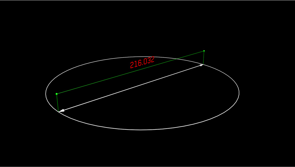
[Closed] Maxscript – autocad style
Hi all:
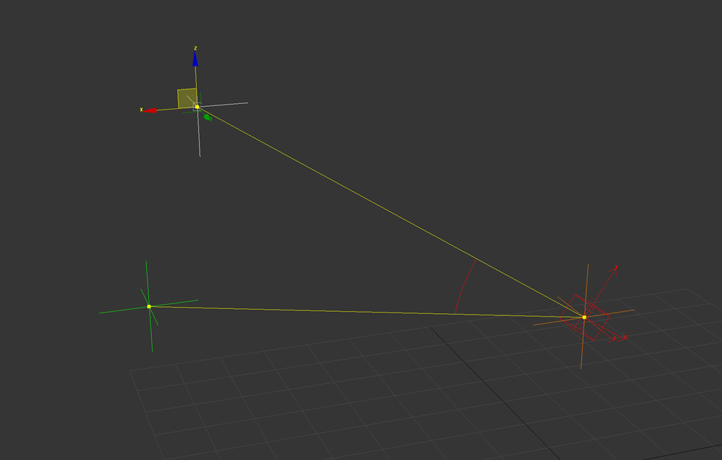
I want help in maxscript, because apparently something in the code that I have made is not working well.
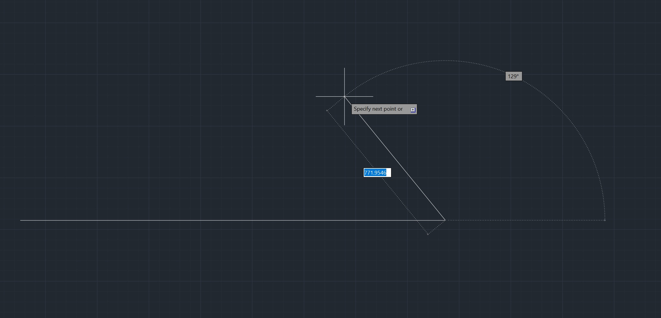
There is conflict with the code, because I cannot place the arc (shape) to imitate the AUTOCAD style.
I want you to tell me that I must modify to achieve interactivity between the position of P2, and the arc. I want to render the autocad stimulus … I know there is a plugin that mimics the autocad style, but it is only for the viewport (for modeling or drawing in 3ds max). I want to render the autocad style.
I attach the code
(
P0 = point name:“P0” pos:[20,20,20] wirecolor:red
P1 = point name:“P1” pos:[220,0,220] wirecolor:green
P2 = point name:“P2” pos:[200,0,0] wirecolor:green
S = Sphere pos:(P0.pos) radius:180 segs:32 xray:true
Obj = Arc name:“TheAngle” from:0 wirecolor:white render_renderable:true thickness:0.5 pie:false
S.parent = P0
fn CreateLine V1 V2 Espesor = (
sp = splineShape pos:[0,0,0] render_renderable:true wirecolor:white thickness:Espesor sides:6 steps:6 render_displayRenderMesh:true
addNewSpline sp
addKnot sp 1 #corner #line V1.pos
addKnot sp 1 #corner #line V2.pos
updateShape sp
animateVertex sp #all
   lista = #(V1, V2)
   --append lista (P1)
   --append lista (P2)
   spm = Spline_IK_Control linkTypes:2 helper_list:lista
   addModifier sp spm
   ep = Edit_Poly()
   addModifier sp ep
)
CreateLine P0 P1 0.4
CreateLine P0 P2 0.4
Ctrl2d=transform_script()
P2.transform.controller = Ctrl2d
Ctrl2d.addNode “P0” P0
Ctrl2d.addNode “P1” P1
txt2d=“R=length(P1.pos-P0.pos)\n”
txt2d+=“B1=normalize (P1.pos-P0.pos)\n”
txt2d+=“Knew=normalize([B1.x,B1.y,0])\n”
txt2d+=“matrix3 [1,0,0] [0,1,0] [0,0,1] (Knew*R+P0.pos)”
Ctrl2d.setExpression txt2d
posCtrl = Position_Constraint()
Obj.pos.controller = posCtrl
posConstraintInterface = posCtrl.constraints
posConstraintInterface.appendTarget P0 100
posConstraintInterface.setWeight 1 100
Lc = LookAt_Constraint()
Obj.rotation.controller = Lc
locConstraint = Lc.constraints
locConstraint.appendtarget P1 100
Lc.lookat_vector_length = 30
Ctrl3d=transform_script()
Obj.transform.controller=Ctrl3d
Ctrl3d.addNode “P0” P0
Ctrl3d.addNode “P1” P1
Ctrl3d.addNode “P2” P2
txt3d=“v1=normalize (P1.pos-P0.pos)\n”
txt3d+=“v2=normalize (P2.pos-P0.pos)\n”
txt3d+=“nv1=normalize (cross v1 v2)\n”
txt3d+=“nv2=normalize (cross nv1 v1)\n”
txt3d+=“matrix3 v1 nv2 nv1 P0.pos”
Ctrl3d.setExpression txt3d
Obj.to.controller=float_script()
Obj.to.controller.addNode “P0” P0
Obj.to.controller.addNode “P1” P1
Obj.to.controller.addNode “P2” P2
Obj.to.controller.setExpression “acos(dot (normalize(P1.pos-P0.pos)) (normalize(P2.pos-P0.pos)))”
Obj.radius.controller=float_script()
Obj.radius.controller.addNode “P0” P0
Obj.radius.controller.addNode “P1” P1
Obj.radius.controller.setExpression “length(P1.pos-P0.pos)”
)
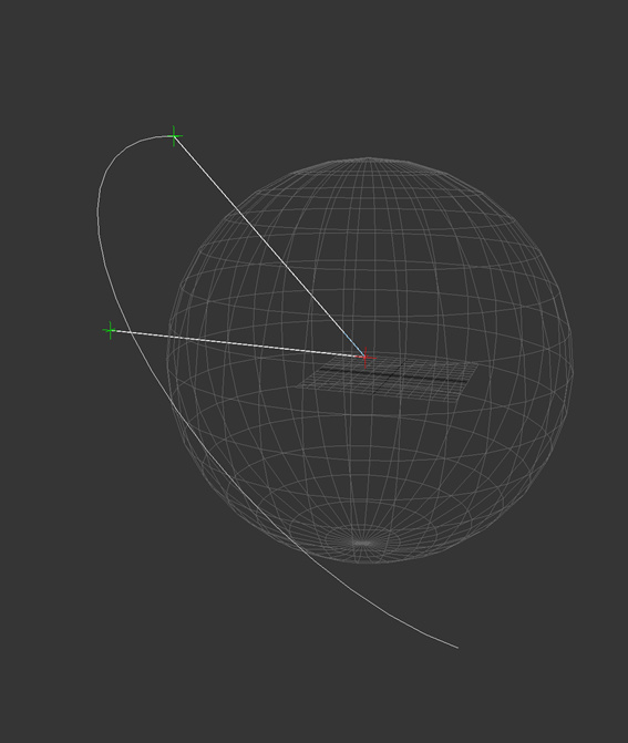
Bad result
I attach the code again
(
P0 = point name:“P0” pos:[20,20,20] wirecolor:red
P1 = point name:“P1” pos:[220,0,220] wirecolor:green
P2 = point name:“P2” pos:[200,0,0] wirecolor:green
S = Sphere pos:(P0.pos) radius:180 segs:32 xray:true
Obj = Arc name:“TheAngle” from:0 wirecolor:white render_renderable:true thickness:0.5 pie:false
S.parent = P0
fn CreateLine V1 V2 Espesor = (
sp = splineShape pos:[0,0,0] render_renderable:true wirecolor:white thickness:Espesor sides:6 steps:6 render_displayRenderMesh:true
addNewSpline sp
addKnot sp 1 #corner #line V1.pos
addKnot sp 1 #corner #line V2.pos
updateShape sp
animateVertex sp #all
   lista = #(V1, V2)
   --append lista (P1)
   --append lista (P2)
   spm = Spline_IK_Control linkTypes:2 helper_list:lista
   addModifier sp spm
   ep = Edit_Poly()
   addModifier sp ep
)
CreateLine P0 P1 0.4
CreateLine P0 P2 0.4
Ctrl2d=transform_script()
P2.transform.controller = Ctrl2d
Ctrl2d.addNode “P0” P0
Ctrl2d.addNode “P1” P1
txt2d=“R=length(P1.pos-P0.pos)\n”
txt2d+=“B1=normalize (P1.pos-P0.pos)\n”
txt2d+=“Knew=normalize([B1.x,B1.y,0])\n”
txt2d+=“matrix3 [1,0,0] [0,1,0] [0,0,1] (Knew*R+P0.pos)”
Ctrl2d.setExpression txt2d
posCtrl = Position_Constraint()
Obj.pos.controller = posCtrl
posConstraintInterface = posCtrl.constraints
posConstraintInterface.appendTarget P0 100
posConstraintInterface.setWeight 1 100
Lc = LookAt_Constraint()
Obj.rotation.controller = Lc
locConstraint = Lc.constraints
locConstraint.appendtarget P1 100
Lc.lookat_vector_length = 30
Ctrl3d=transform_script()
Obj.transform.controller=Ctrl3d
Ctrl3d.addNode “P0” P0
Ctrl3d.addNode “P1” P1
Ctrl3d.addNode “P2” P2
txt3d=“v1=normalize (P1.pos-P0.pos)\n”
txt3d+=“v2=normalize (P2.pos-P0.pos)\n”
txt3d+=“nv1=normalize (cross v1 v2)\n”
txt3d+=“nv2=normalize (cross nv1 v1)\n”
txt3d+=“matrix3 v1 nv2 nv1 P0.pos”
Ctrl3d.setExpression txt3d
Obj.to.controller=float_script()
Obj.to.controller.addNode “P0” P0
Obj.to.controller.addNode “P1” P1
Obj.to.controller.addNode “P2” P2
Obj.to.controller.setExpression “acos(dot (normalize(P1.pos-P0.pos)) (normalize(P2.pos-P0.pos)))”
Obj.radius.controller=float_script()
Obj.radius.controller.addNode “P0” P0
Obj.radius.controller.addNode “P1” P1
Obj.radius.controller.setExpression “length(P1.pos-P0.pos)”
)
Thanks for the reply.
I’m going to review it carefully, and I write.
Thank you
Dennis:
I am impressed with the code you have submitted, it is very versatile. I’m going to add control to the Radius of the Circle.
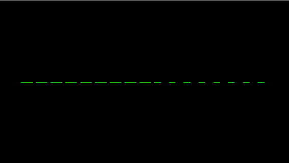
Do you know how I can make a “Dash Shape” ???, this is common in AUTOCAD
Thank you very much indeed.
Dennis:
Thanks to your support I have been able to make a similar script. Again, how can I make “Dash Shape”?
Thanks friend
you can’t make a “dash” shape. But you told above about the rendering… So you can render it ‘dashed’ by applying proper UV map and material which might look ‘dashed’ in views as well.
Of course you can subdivide any shape as much as you like, and hide every even segment… but is it worth doing really nonsense?
Denis:
The code that you have put for the Arc between the lines is very instructive. But I still have problems for putting more than one “controller” at the same point. I’ll keep trying and let you know.
Thank you
Hi Denis:
I want to place the text of the angles in the center of the arcs. Do you recommend using PathDeform or PathConstrain?
What would be the best option (PathDeform or PathConstrain)?
Note: Text should have a good orientation for the camera.
Thanks Denis, you are good at Maxscript. An applause.
What will it be? Some kind of visual illustration, tutorial?
Sure that everything can be done in 3DS MAX, but it’s too complicated … I would do axes, angles, arrows in MAX, and in Adobe After Effects (for example) add labels.
All labels must face the camera and have the same font size (not scalable). It takes a pretty clever constraint that isn’t built-in. The best built-in implementation is a Scripted Manipulator (which is not easy to make renderable).
Hello Denis:
I have created the script that generates the Dash Line. Can you give me support on how to place this code in Pos.controller in the points, the idea is:
I move the Point and the Dash is modified…
--Creating Big Line
SplineTarget = splineShape pos:[0,0,0] wirecolor:white name:"Spline_Target" render_renderable:false
addNewSpline SplineTarget
addKnot SplineTarget 1 #corner #line [0,0,0]
addKnot SplineTarget 1 #corner #line [100,100,0]
updateShape SplineTarget
animateVertex SplineTarget #all

WidthDash = 4 as integer
GapDash = 2 as integer
L = CurveLength SplineTarget as integer
CantidadDash = floor(L/(WidthDash+GapDash))  -- Integer
Dash=#() --Array for Spline small
ArrayPercent = #()  -- Array for Percent
-- Creating Dash Lines and Array of Percent
for i=0 to CantidadDash do
(
append ArrayPercent (i*(WidthDash+GapDash)) -- Generating list of Percent
append Dash (sp = splineShape pos:[0,0,0] wirecolor:green name:("Dash"+i as string) render_renderable:true thickness:1 sides:6)
addNewSpline sp
addKnot sp 1 #corner #line [0,0,0]
addKnot sp 1 #corner #line [0,0,WidthDash]
updateShape sp
animateVertex sp #all

)
